Showing posts with label boatbuilding. Show all posts

Tuesday, May 17, 2022

What's in Your Ditch Bag?

New Tech Bights article now out in issue No. 135 of Small Craft Advisor magazine.


Monday, March 21, 2022

What's All This About AIS?

My latest Tech Bights article, on the basics of AIS, is now out: Small Craft Advisor No. 134, March/April 2022.


If you're thinking about buying a new handheld VHF radio, you might want to consider ICOM's M94D, which comes with an integrated AIS receiver.

Thursday, December 9, 2021

What's All This About Electric Outboards?

2021 was an interesting year for electric outboards. In the spring Mercury announced that they will launch a new line in 2023. Then Yamaha debuted their HARMO electric outdrives at the IBEX (International BoatBuilders’ Exhibition) in September. A couple of relatively unknown companies also showed prototypes of high-power electric outboards. Now that General Motors has decided to pursue electric boat building (“GM Acquires 25 Percent Stake in Pure Watercraft to Accelerate All-Electric Boating,” 11-22-2021), it’s time to get serious about electric outboards…


(Pure Watercraft photo)


Advances in high-efficiency motors and lithium-ion battery technology are slowly finding their way into electric-powered boats. Since we normally think in terms of “horsepower,” maybe it’s also time to recalibrate how we think about an electric outboard’s power. How do you measure horsepower, anyway? (OK. One horsepower is equal to 550 pounds of force to move at a speed of 1 foot per second; or if you’re on a boat, 65 lbs of drag at 5 knots…). Electrical power is easy to accurately measure -- voltage times current, or watts. Torqeedo rates their 3-kW motors as equivalent to 6-hp gas outboards; and their 10-kW motors to 20-hp outboards. So if you really can’t make the switch, take the peak power of an electric outboard in kilowatts, and then double it to get a (very) rough idea of the equivalent horsepower. In the end, however, whether it's a gas or electric outboard, the thrust exerted by the propeller -- in pounds of force -- is what actually gets (and keeps) the boat moving. That’s the number we’re really looking for; and it’s obvious that it depends on more than “power.”


Besides Mercury’s and Yamaha’s plans to produce electric outboards, as noted above, we can reasonably anticipate that other established manufacturers like Honda and Tohatsu will soon include electric outboards in their lineups, and possibly transition to fully-electric at some point. A couple of long-shots worth watching announced their plans at the 2021 IBEX show. Rhode Island-based Flux Marine (www.fluxmarine.com) will introduce 15, 40, and 70 hp electric outboards in 2022. And Vision Marine (www.visionmarinetechnologies.com), a Canadian company that is now listed on the NASDAQ, claims they will begin delivering “the world’s most powerful outboard” – their 180-hp eMotion – to OEMs. [Coincidentally, Evinrude, which was owned by Quebec-based BRP (Bombardier Recreational Products), branded their high-efficiency, high-output gas outboards “E-TEC.” And BRP exited the outboard business in 2020.]


But Pure Watercraft (www.purewatercraft.com), a Seattle-based tech start-up, might be the closest to actual production. Back in 2010, after the Great Recession, Pure Watercraft got venture capital to develop and manufacture a 25-kW electric outboard and integrated battery pack. They used the playbook from Tesla Motors, starting with a clean sheet design, developing their own PMAC (permanent magnet alternating current) motor and gearbox, and building a bunch of not-for-sale prototypes from components and systems they produced in-house. The Wye Island (MD) Electric Boat Challenge is a 24-mile circuit that has been run every year since 2001; and in 2017 Pure Watercraft finished the course in just over an hour, setting the course record – still unbroken – with one of their prototypes (see “Wye Island Challenge – An Epic Marathon” in their website blog). At the end of 2021 GM invested $150M in the company, apparently as part of its plan to diversify beyond automotive applications.


Each of these start-ups listed above began taking reservations at the end of 2021 for their as-yet-unreleased outboards. The $64 question now is, Who will deliver the goods? But I think the biggest unknowns are how exactly GM will leverage their investment in Pure Watercraft; and if other automotive manufacturers will pursue similar deals of their own. We can anticipate that lower-cost, higher-performance lithium-ion battery technology will continue to benefit from the economies of scale that automotive manufacturers and suppliers bring to the table.


www.businesswire.com/news/home/20210928005812/en/Yamaha%E2%80%99s-HARMO%C2%AE-Electric-Outboard-System-Makes-U.S.-Debut-at-IBEX


www.soundingsonline.com/news/mercury-announces-plans-for-electric-outboards


Sunday, November 14, 2021

More Small Boat Power

My latest article in Small Craft Advisor No. 132 (Nov/Dec 2021) is out. Lots of information of the current status of the drop-in lithium iron phosphate batteries that you can use to replace a lead-acid battery. Why it might be useful, and why it might not be worth it the cost.

Monday, August 30, 2021

Small Boat Power

My article on adding electric power on your small boat is now published in Small Craft Advisor, Sep/Oct 2021, No. 131. I used a couple of low-cost sealed lead-acid batteries -- and a small solar module for on-water charging -- to power my GPS/depth gauge, run a fan during humid nights at anchor, and charge my other stuff.

My column in the next SCA issue will continue this thread with a discussion of "drop-in" lithium-ion-iron-phosphate batteries that can upgrade and even simplify the system.

Friday, August 13, 2021

Recycling a Racing Dinghy -- Part 1

A few years ago I acquired a little Penguin dinghy for teaching. My boat has a fiberglass hull and an aluminum mast, but the Penguin was designed almost a century ago, and most of the Penguins were/are fabricated using plywood and have wooden masts. Although Philip L. Rhodes originally drew the 11-½ foot dinghy’s lines for a design competition (it lost), the Penguin’s story actually begins five years later, in 1938, with a request by a group of Potomac River dinghy sailors for a small, car-toppable racing boat that could be easily constructed by amateur boatbuilders. Rhodes already was a well-known naval architect and would design many of the first-generation fiberglass dinghies produced by O’Day (the Sprite, Widgeon, and Mariner) as well as Dyer’s Dink and Dhow, among many other boats. For his Chesapeake Bay clients, Rhodes supplied plans for a stable single-chine catboat that could be constructed using low-cost boatbuilding materials -- waterproof plywood and resorcinol glue -- which, at that time, were considered “state-of-the-art.”

(from the Penguin Class photo gallery)

While the process of laminating thin layers of wood -- plywood -- was actually invented in the mid-1800s, it was not until the early 20th century that high-speed rotary lathes were designed that could produce the thin veneers needed for large-scale plywood manufacturing, which developed around the fir and spruce forests of northern California, Oregon and Washington. Propelled by the rapidly growing automobile industry, by 1929 there were more than 17 plywood mills on the West Coast. And when new waterproof glues were introduced in 1934, plywood became an interesting new construction material for boatbuilding and for many other exterior applications (from the APA History). Rhodes now took advantage of large-area sheets of waterproof plywood to produce plans for a single-chine dinghy constructed using “developed panels” that were attached to a relatively light-weight internal framework. The technique is used extensively by Phil Bolger, Jim Michalak, and many other designers to produce easy-to-build small boats. And the bible on epoxy and boat building, “Gougeon Brothers on Boat Construction” (5th Edition, 2005), has a detailed description of “compounded plywood” design (Chapter 25). But Rhodes was probably the earliest designer to take advantage of waterproof plywood to simplify small boat construction.

The Potomac River sailors built a dozen of Rhodes’ plywood dinghies to test the design. And Hull No. 1 was displayed for many years at the Chesapeake Bay Maritime Museum in St. Michaels, MD. When plans were published in Yachting magazine in 1940, interest in the Penguin surged, and racing fleets were established on both coasts and around the Great Lakes. Although competition paused during WWII, by 1955 there were more than 100 Penguin fleets. And according to Chris Museler, more than 9,700 Penguins have been built.


With a plumb bow, hard chines, high sides, and 72 square feet of sail, the two-person Penguin dinghies are dry, stable boats. Right from the beginning they were campaigned through the fall and winter seasons, and the Penguin excelled at frostbite racing until tippier and wetter Lasers eliminated the need to find a crew willing to freeze and dry suits replaced wool sweaters and oilskins. The Penguin’s Portsmouth Number rating (D-PN) is 111.5 -- not fast, but not too shabby, either. For comparison, the lateen-rigged Sunfish is rated at 99.6 (lower is faster), and the Laser -- which is quite a bit faster and much higher-strung -- is rated at 91.1. Today there are only a few surviving Penguin fleets, and class racing is centered on the Chesapeake Bay, very close to where it all started (see the International Penguin Class Dinghy Association (IPCDA) website, www.penguinclass.com).

Now it turns out that I’ve got one of the last Penguins built (hull number 9744), a fiberglass boat that was constructed by Lightwave Yachts (aka Innovator?) in Florida in 1995. It’s a “self-rescuing” design, with integral flotation chambers between the hull and the deck; and it has a light, tapered aluminum mast. The only wood on it appears to be in the gunwale cores.


It had been listed for sale on the Penguin class website, but apparently there was no interest from racing skippers who apparently prefer the traditional wooden hulls, which do not carry a 20-pound weight penalty. I found my Penguin for sale on Craigslist and bought a clean boat with top-of-the-line hardware, a roadworthy galvanized trailer, and a crisp North “training” sail. Since I’m not interested in competition anymore, my annual summer boat project is focused on incorporating changes that would transform a classic racing dinghy, typically sailed with a crew of two, more sailor-friendly and capable of being safely managed single-handed. And in the bargain keep an obsolete and unwanted hull (and sail) with lots of useful remaining life out of the landfill.

Sunday, July 4, 2021

Comparing the Force 5, Laser, and Sunfish

The Force 5 dinghy was designed by Fred Scott and Jack Evens in 1972, around the same time that Bruce Kirby and Ian Bruce designed and developed the Laser. At one point both boats competed for the same sailors who grew up racing the Sunfish, with it's iconic and simple -- but effective -- lateen rig. With its roots as a home-built boat constructed from plywood, the Sunfish is hard-chined, with high initial stability, and it can plane under the right wind conditions with a skilled sailor. The Laser and Force 5 were designed from the ground up to be molded from fiberglass. Their chines are rounded, their bows are much sharper, and their stability is much more dynamic and sensitive to crew weight. Both of these next-generation, cat-rigged dinghies are capable of planing and of sailing faster than the Sunfish. 


When Kirby introduced his Laser at the New York Boat Show in 1970 there was a groundswell of interest -- and more than 100 orders. But without the means to manufacture the Laser in volume, Kirby licensed the rights to established builders in three separate geographic regions -- Europe, North America, and rest of world. Although he imposed "one design" restrictions along with the licenses, Laser variations proliferated, mainly in Europe. In contrast, the Force 5 was designed and produced by AMF, who dominated the bowling equipment market after World War II. Over a couple of decades of growth, AMF diversified by acquiring a raft of recreational product companies like Harley-Davidson motorcycles, Head skis, and Ben Hogan golf clubs. In 1969 AMF acquired the Alcort sailboat company, which had been founded in 1947 by Al Bryan and Cort Heyniger to produce the original Sailfish sailboard, and which introduced their blockbuster fiberglass Sunfish dinghy in 1960. Under AMF, the Alcort subsidiary produced a series of recreational sailboats. Some were hits -- the Apollo sloop (also designed by Kirby), Minifish (a smaller, cheaper version of the Sunfish), Puffer (from Scott), Sunbird (Scott and Evans), and the Zuma. Other AMF designs became historical footnotes -- the Hilu (a proa), the Tiga (windsurfer), and the Trac catamaran.

AMF, like many other companies that had gone on acquisition sprees during the 1960s and 70s, began to break up and sell off their subsidiaries during the high-inflation 1980s. According to the Sunfish class history, AMF's small boats were spun off into a reconstituted "Alcort Inc" in 1986. And two years later in 1988, Pearson Yachts, which itself had been split off from the Grumman conglomerate (still famous for their aluminum canoes and rowboats), bought Alcort -- and O'Day and Cal Boats (aka, Jensen Marine). Separately Pearson also acquired the rights to produce the Laser from Vanguard, the original manufacturer licensed in North America. But in 1991, rocked by an economic recession and the impact of a 10% luxury tax on boat purchases, Pearson declared bankruptcy. SunfishLaser Inc ("SLI") was then created (under Peter Johnstone, son of Bob Johnstone, the founder of J Boats, and with significant funding from North Sails -- the authorized Laser sail supplier) to produce AMF's best selling products, the Sunfish, the Laser, and the Zuma. 

Since the Laser and the Force 5 were so similar in size and performance, SLI in effect killed the Force 5 in order to focus all commercial and racing attention on the Laser, which, based on its Portsmouth ratings, is the faster of the two. The Laser also became an Olympic class boat in 1996, and more than 200,000 boats have now been built. SLI sold the Force 5 design rights to Weeks Boat Yard (in 1994) who continued to produce boats that improved upon the AMF design. Altogether, maybe 15,000 Force 5's have been built, a stark contrast to the order of magnitude greater number of Lasers produced since it's introduction in 1971. But it turns out that Alcort's first racing dinghy -- the Sunfish -- is still the production champ; more than 300,000 Sunfish were built as of 2001, it's 50th anniversary. This year, 2021, is the Laser's 50th anniversary; and with current worldwide production at less than 2,000 boats a year, there's little chance that the Laser will ever surpass the Sunfish as the production king of racing dinghies.


Here are some comparative specifications for the Force 5 and the Laser, as compared to the Sunfish...from SailboatData.com

Sunfish
Length, overall, 13'-9"
Length, waterline, 13 feet
Beam, 4'-1"
Weight, 120 pounds
Sail area, 75 square feet
D-PN Rating, 99.6
Displacement/Length ratio (prismatic shape): 26.2
SA/Displacement ratio (power to weight): 47.0 
Brewer comfort ratio: 2.31
Capsize screening ratio: 3.23

Force 5
Length, overall, 13'-10"
Length, waterline, 13'-2"
Beam, 4'-10"
Weight, 145 pounds
Sail Area, 91 square feet
D-PN Rating, 95.4 (lower is faster)
Displacement/length ratio: 27.3 (lower is better)
SA/Displacement ratio: 54.0 (higher is better)
Comfort ratio: 1.98 (higher is more comfortable; racing boats are less than 20)
Capsize screening ratio: 3.72 (higher is more stable)

Laser
Length, overall, 13'-9"
Length, waterline, 12'-6"
Beam, 4'-7"
Weight, 130 pounds
Sail Area, 76 square feet
D-PN Rating, 91.1
Displacement/Length ratio (prismatic shape): 26.4 (better than Force 5)
SA/Displacement ratio: 47.4 (lower "power/weight" than Force 5)
Brewer comfort ratio: 2.01 (about the same as Force 5)
Capsize screening ratio: 3.60 (less stable than Force 5)


All of these dinghies have unstayed aluminum masts. As mentioned above, the Sunfish has a lateen rig. The mast is 2-1/4 inches in diameter and is only 10 feet long, while the gaff and boom spars, 1-1/2 inches in diameter, are both 14 feet long -- a big disadvantage when transporting the boat. The Force 5 and the Laser were both designed as sloop-rigged cats with sleeved sails. The Laser mast is 20'-2" in length. The Force 5 mast is 21 feet long. Both the Force 5 and the Laser have multi-part aluminum masts. The Laser is in two parts; the base is 9'-5" and the top section is 10'-11" long. The Force 5 mast comes in three parts, and the longest section is 9'-10" long. The base section for both masts is 2-1/2 inches in diameter, so a Laser rig will fit into a Force 5 mast step, and vice versa. I have found, through experience, that it's important to have the boat on the ground before you try to step the mast (with sail) on either the Laser or the Force 5. The boom for both rigs is 9 feet long; the outhaul on the Force 5 is internal, whereas the Laser uses lower-cost external lines and blocks. Since all the spar components are shorter than the boats, it is much easier to transport a Force 5 or a Laser than a Sunfish.

The sail dimensions, from the Sailrite (www.sailrite.com) database, are as follows. For the Laser: luff = 16.5 feet; foot = 9 feet; leech = 18.32 feet. For the Force 5: luff = 17.75 feet; foot = 8.62 feet; leech = 19.27 feet. As mentioned above, the Force 5 sail has 20% more area (15 SF) more area than the Laser (76 SF).

The mast "bury" on both the Laser and the Force 5 is 14 inches. On the Force 5 the boom height above the deck is 19 inches. The boom height on the Laser and the boom height of a Laser rig on a Force 5 hull (the latter verified by actual measurement) is about 23 inches, or 4 inches higher than the Force 5 boom.

The original Force 5 from AMF was built with four clam cleats on the foredeck to handle the cunningham and downhaul lines. The Laser has deck-mounted cam cleats that are typically used during racing for the downhaul and the outhaul (no cunningham). Both boats have their sheet rachet blocks located mid-boat, just aft of the daggerboard trunk. The Force 5 has a traveler attached to a thwart across the cockpit. The original Force 5 is set up for boom-end sheeting with a fixed traveler line across the aft deck, while later versions have two blocks in the middle of the boom for the sheet directly above a multipart rachet block. The Laser uses boom-end sheeting and has a simple tensioning adjuster for the traveler line (an advancement over the simple fixed traveler used on the Sunfish).

The foils on AMF's Force 5 are constructed of solid mahagony. Based on the class rules, the daggerboard's maximum chord is at 36% of it's width (3-3/4 inches of the 11.75 to 12 inches width limit). The rudder surfaces are flat and parallel except it can be profiled within 1-1/4 inches of the trailing edge. The Laser foils are composite construction. The class rules do not specify the foil cross-section, but a measured daggerboard's maximum chord is at 1/3 of it's width (11 cm over 33 cm, or 13 inches, in width). The shape of the Laser's daggerboard and its rudder is much more streamlined NACA profiles (probably NACA 0010 and 0012). Both boats have kick-up rudders; the Force 5 rudder is "spring-loaded" and does not work very well, so it does not need a downhaul. The Laser's rudder blade does have a downhaul line. 

One of the biggest design differences between the two hull designs is that, due to its large footwell, the Force 5 can comfortably accommodate a crew of two even though it was designed for single-handed sailing, whereas the Laser cannot. I suspect that the Force 5 is more comfortable to sail even if you are sailing it single-handed. Lasers "wear out" when the deck becomes "spongy" -- especially prevalent on Lasers sailed by heavier skippers. The Force 5 is designed and built, by comparison, much stiffer than the Laser and should not have that particular issue. Look for holes and flex in the bottom rather than soft decks.

Because the Laser is still being built and it remains a popular teaching boat, as well as an Olympic class boat, it's easy to find literally any part, and new "class legal" sails are readily available. You can also find "practice" sails for just a few hundred dollars (www.intensitysails.com). But if you need rare parts such as a mast or boom for a Force 5, your best bet might be to find another Force 5 and cannibalize it (older boats sell for under $500). You can get a "zipper luff" sail ("class legal" and $635 in 2010, the date on their parts list) from Weeks Boat Yard, if they are still in business when you call. But a "practice" sail from Intensity Sails is less than $200.

References


"The story of the former Olympian who designed the world's more beloved boat," Popular Science, 2019,  https://www.popsci.com/bruce-kirby-laser-sailboat/

Monday, April 19, 2021

"The Evolution of Ships" -- the miniature ships of August F. Crabtree

The Mariner's Museum (https://marinersmuseum.org/) in Newport News, VA, is well know for many great exhibits and resources. If you are a fan of Chris-Craft boats, they are THE archive with hull cards, photos, boat plans, sales catalogs, price lists, boat and engine manuals (https://marinersmuseum.org/library/#chris). They are working on stabilizing the gun turret of the first ironclad, the Monitor (https://monitorcenter.org/)

Less well know, perhaps, are the model ships built by August Crabtree and his wife, Winnifred. Here's an excellent YouTube video of a talk that Ron Lewis, a docent at the museum, recently gave on his life and work...https://www.youtube.com/watch?v=X3F5snoOXDU

Sunday, February 14, 2021

Old Marine Engines -- Part 2: Ignition

KISS -- Keep It Simple (add your own second "s")...

My previous post gave a brief history of the early 2-stoke marine engines. Stan Grayson, who wrote "Old Marine Engines: The World of the One-Lunger," noted that even though they were relatively expensive, they were quickly accepted among the working watermen because they provided a competitive advantage -- and were useful when the wind and the current did not cooperate. And they were simple -- to operate and to maintain.

Before there were reliable spark plugs, and even after, there were alternate ways to ignite a compressed charge of gasoline or kerosene. Of course, Rudolf Diesel had developed his sparkless engine -- which depended on high compression pressure (at least a 15:1 compression ratio) to generate the temperature required to ignite the vaporized fuel (his first patents were granted in 1892; the first diesel engine ran in 1897). But the easy-to-build and easy-to-maintain 2-stroke engines in the early 1900s were not high compression engines -- the development of non-leaking seals and strong materials is a science as well as an art (and living with leaky shaft seals is quite acceptable to most boatmen, even today). The early 2-stroke engines utilized the relatively low-pressure piston and seal technology and were designed to produce moderate compression ratios, in the range of 3:1 (easy to crank over) to 6:1 (very tight). In fact, Grayson notes that it was possible to replace a blown head gasket with material at hand while out on the water. Not the best situation, for sure, but possible. The early engines tended to be overbuilt, with steel pistons and extra metal in the castings, which most certainly reduced the number of manufacturing rejects. Weight was a factor, but not a limiter, and some of the engine builders did not even bother to quote weight. And the extra iron certainly helped if the cooling pump was beginning to limp a bit. 

Compression ratios -- Old Marine Engine discussion board: www.oldmarineengine.com/discus/messages/3430/7949.html

With lower-compression engines there was plenty of space for a charge deflector -- sometimes just a piece of angle iron bolted to the top of the piston -- to enhance exhaust evacuation. And there was room for the spark source, even with a simple flat head. The old marine 2-stroke engines basically used one of two ignition sources: "make-and-break" igniters; or spark plugs. Both had their advantages and disadvantages and Grayson breaks it down as "low tension" (that is, low voltage) versus "high tension." The former is a mechanical "sparker" solution, perfect for a simple engine. Here's a nice video of a make-and-break Acadia Atlantic running along. Try slowing the video down so you can see the operation of the mechanical mechanism at the top of the cylinder that is driven by an eccentric near the flywheel. Seems like a pretty complicated mechanism to me. But...it would also seem to be relatively easy to repair or adjust with a couple of basic tools, and without a lot of high-tech training. And since it operates at low voltage (like around 6 volts), it can get liberally doused with seawater -- and still work; the parts that actually spark are all inside the cylinder. Corrosion of the connections -- easily observed and remedied -- were the biggest electrical issue, once the mechanical contraption was adjusted correctly. But since the igniter is a mechanism with lots of bits and springs, how long will it work before it needs additional adjustment; or before something breaks? 

For those of us who grew up with points and plugs, it's not immediately obvious how exactly this make-and-break ignition system works. Here is one description, dated 1906, by K.K. Williams, E.E.

"Without the aid of a coil, no spark can be produced that is large enough to ignite the gas when using batteries to generate the current for either [make-and-break or jump-spark] system. The make-and break coil consists of one continuous winding of coarse insulated wire wound over a soft-iron core. When the electricity passes through the coil, and the circuit is suddenly broken — that is if two wires are separated after being connected — a spark of high intensity follows the break or gap for a very short period of time. To produce the spark in the cylinder a mechanical motion is imparted to one electrode or end of the wire as it might be, at the proper point in the revolution. The moving electrode touches the stationary point, to permit the current to flow, forming a circuit, just before it is broken.

The important point here is that the actual make-and-break igniter, shown below, is a pretty simple mechanical device that bolts onto the top of the cylinder. AND, it has to open quickly to create the "spark", actually the arc across an interrupted electrical circuit. As you can see on the igniter below, the part with the springs (on the outside) rotates to strike a stationary "anvil" inside the cylinder (kind of reminds you of an old flintlock rifle striker mechanism). On this igniter, it looks like the stationary "hot" electrode is electrically insulated from the base so that the rotating hammer is a simple close-clearance sleeve.


"Make-and-break spark as ordinarily utilized requires a large voltage as generally compared with jump-spark, and uses more at each time of ignition or contact, because the contact is made during a certain length of the revolution. This makes the make-and-break system stem utilize a larger amount of battery power per hour than the jump-spark, as will be explained further on in this article.
 
"The spark generated by using the make-and-break system is. however, larger and hotter than the jump-spark. Properly designed, an advancing arrangement can be made to advance and retard the spark through the same useful portion of the revolution as jump-spark, but very few designers seem to care to arrange this important feature of the make-and-break system, being satisfied to set the spark at one point in the cycle, and generally not being able to change unless the engine is stopped. The hammer type of make-and-break has given very good service. The power to be derived from a gas engine is proportionate to the proper combustion of the gases.
 
"Make-and-break gives the hotter spark [and] consequently more power [than jump-spark] because it ignites the gas more quickly. It gives a very instantaneous ignition and less advance is required. because the action is quicker than jump-spark. Then again, this system has only one circuit and is easily understood  by the novice and appeals very readily to the beginner.

"Make-and-break advantages are: it's simplicity, using one circuit; a test of the battery circuit is a test of the sparking circuit; ignites the gas quickly and thoroughly; low voltage circuit; not readily effected by spray or rain; and coil not easily burned out. Its disadvantages are: working parts in the cylinder firing chamber; loss of compression sooner or later through the movable electrodes bearing; inaccessible generally, although not always, to advancing the spark; requires setting regularly; sparking points wear; springs cams, levers rods; and requires an unnecessary amount of battery current. The claim of unnecessary amount of battery is better explained in considering that ten times more current -- or the time of ignition is ten times longer -- at 100 rpm than at 1,000 rpm, with a waste of 9/10th of the battery power at the former speed.

While it's not a marine engine, here are a couple of great videos of the innards of a 1908 Matheson automotive engine that has a make-and-break ignition, www.youtube.com/watch?v=egbCVxAKvX0The second video shows the same engine "sparking" -- the sparks look pretty "fat." This ought to convince you that, once all the adjustments are right, the make-and-break ignition works very well, www.youtube.com/watch?v=KZyuCpoXYgU


In contrast to the mechanical, low-voltage make-and-break ignition discussed above, jump-spark engines use spark plugs and points. And they require step-up coils to generate high-voltage sparks. They are what we grew up with in our cars. Williams continues...
 
"Comparing the two systems. jump-spark advantages are its accessibility to advancing and retarding; consumes less electricity; the strength of the battery can be determined by the vibrator's action; requires no engine apparatus such as rods, cams, springs, levers; the plug screws into the cylinder leaving no possible means for loss of compression to be traced to this source; and jump-spark ignites the gas more readily in starting because the points are so small that heat enough is generated to warm the gas at the flame.
 
"The disadvantages are: leaks in secondary or high tension circuit; cracked or fouled plugs; a positive current in the primary circuit is no guarantee of a spark occurring at the plug points; liability of burning out the secondary winding if too many batteries are in circuit; lags slightly at high speed requiring a further advance than make-and-break; spark-plugs carbonize; is affected by dampness or moisture, such as rain or spray; and extreme high compression blows out or insulates the spark.
 
K.K. Williams, E.E., "Make-and-break versus Jump-spark", Powerboat News, Volume 2, No. 4 (August 26, 1906), www.oldmarineengine.com/technical/MBvsJS.htm

John Davis' video of his Detroit Engine Works motor is a great demonstration of a 2-stroke spark engine and how it operates. Notice how he can use the advance lever to easily reverse the rotation -- no gearbox needed. KISS.

-------------------------------------

If you are still curious about make-and-break ignitions, here are some more resources that you can check out:

"Internal Combustion Engines and Tractors, Their Development, Design, Construction, Function and Maintenance," notes of a series of lectures, delivered by Oliver B. Zimmerman of the Engineering Staff, International Harvester Company, Chicago, 1920.
www.gasenginemagazine.com/gas-engines/function-ignition-apparatuses-engine-systems/

A more contemporary EEs take on the old engine ignitions and how they operate, see David Cave's article in Gas Engine Magazine (Sept 8, 2000) 

Hooking up a make-and-break motor, www.youtube.com/watch?v=yWINn34ixPQ

In addition to Stan Grayson's book and whatever information I could find via Google, I have used photos of old motors from several messabouts and museums around the Chesapeake Bay. I need to give a shout out to the Upper Bay Museum in North East, MD, which has a nice display of early small marine motors, both outboards and inboards. Finally, the absolute best place (in my opinion) to see restored and working old marine motors is at the Calvert Marine Museum (Solomons, MD) Maritime Festival that is scheduled for May 1, 2021Collectors come from across the country, but it's still a very accessible and low-key gathering, and much easier to get to (and less expensive) than the show in Mystic Seaport, CT. And the best place to research the old 2- and 4-cycle engines is the Old Marine Engine discussion forum.

Thursday, February 11, 2021

Old Marine Engines -- "One Lungers" (Part 1)

My oldest outboards are "only" 70 or 80 years old, and I've worked on a few that were closing in on 100 -- and they still ran. But I never got a chance to spend much time on the 2-cycle (2-stroke) marine engines that the watermen bought to replace oars and sails -- before there were outboards. They are rare today, but people still find them and get them running. Here's a good place to find out more about them: www.oldmarineengine.com/index.html.

It might be surprising to learn that gasoline engines were invented almost 150 years ago, shortly after the Civil War. In 1859, before the war, Edwin Drake drilled the first oil well in Titusville, PA. The "black gold" was used to produce kerosene -- to replace whale oil that was used for lighting. The lighter, more flammable components, like gasoline and naptha, were discarded. And the cheap waste products presented a brand new opportunity...

The earliest engines to use gasoline looked very similar to steam engines and began to be built around 1872 (Brayton cycle, oldmachinepress.com/2016/12/05/brayton-ready-motor-hydrocarbon-engine/). After 14 years of development, Nicholaus Otto and Eugen Langen produced the first gas compression engine in 1876. These were heavy engines, like 1,000 pounds per horsepower, and were mainly used for "instant start" stationary applications, replacing steam engines that took hours to fire up.

In 1885 Gottlieb Daimler, who had helped develop Otto's compression engine, patented a lightweight, four-cycle gas engine -- around 200 pounds/hp. The first modern automobile was invented by Karl Benz -- or by Daimler and his colleague Wilhelm Maybach depending on who you believe -- in 1886. Before too long there were hundreds of big and small shops building engines. Ford produced his first gasoline-powered automobile, the "Quadricycle" (not the Model T), ten years later in 1896; the mass-produced Model T didn't show up until 1908. 

Aluminum, 40 per cent lighter than cast iron, was more expensive but widely available beginning in the 1890s. The Wright brothers built their own lightweight gas engine, with a cast aluminum block, and flew at Kitty Hawk in 1903. Their engine, with oil and cooling water, weighed about 180 pounds and produced at least 12 horsepower (15 pound/hp).

https://wrightbros.org/Information_Desk/Just_the_Facts/Engines_&_Props/1903_Engine.htm

Once Daimler demonstrated that powerful gas engines could built at less than 200 pounds/hp, applications for them rapidly expanded. So when Ole Evinrude began to produce outboards in 1909 there were already plenty of gasoline-powered contrivances around the farm, on the dirt roads (the Lincoln Highway that crossed the country project didn't get started until 1913), in the air, and on the water. With weight of the engine hanging out on the transom, outboard motors put greater emphasis on lightweight materials (i.e., aluminum), simple valveless 2-stroke designs, and higher compression ratios for more specific power. In the 1920s outboard motors weighed in at around 20 pounds/hp. By the 1950s non-racing outboards typically weighed less than 10 pounds/hp, and the larger displacement outboards (which was around 25 hp at that time) were less than 5 pounds/hp.

Now back to the waterman's cast-iron engines...Stan Grayson wrote "Old Marine Engines" in 1985 and you can still find copies of it listed on Amazon (for over $900 new? I got mine for a LOT less). And Grayson notes that Union Gas Engineering, which was "affiliated" with the Philadelphia engine builder, Globe, produced a 4-cycle engine with a make-and-break ignition in 1884. And Globe added marine engines to their product line starting in 1886. Apparently they were a big hit. The "horseless carriage" makers also jumped into the fray, building 4-cycle gas engines for marine applications. Grayson lists Winton, Lozier, Stanley (of steamer fame), Simplex, Duesenberg, and Buick. All well and good for big yachts with hired mechanics. Not so good for DIY watermen and farmers.

Simple is reliable; simple is cheap. While the 4-cycle required valves, like the steam engines they replaced, a 2-cycle engine eliminated the complicated valve train, reduced the parts count, the complexity of assembly, and the costs -- to assemble and to maintain. And the 2-cycle engine was amenable to construction by even small machine shops. Grayson says that there were thousands of shops producing marine motors. The most well-know engines of that era, at least by the number that didn't end up as anchors or wartime scrap, are Palmer, Acadia, Luenberg, Lozier, Mianus, and Standard.

Here is a video of a 2-cycle Acadia engine with a make-and-break ignition, https://www.youtube.com/watch?v=cQrpp0dtV7o

A few years ago I had an opportunity to get some photos of old single-cylinder motors that were found around the upper Chesapeake Bay. The motor shown below is a 2-cycle, 2-hp "Sandow" built by the Detroit Motor Car Supply Company in Detroit, MI around 1910. It looks like it has the original paint and the original Schebler carburetor (on the left side), and it still turns over. Note the priming cup and the broken spark plug at the top of the cylinder. The "buzz box" ignition coil is missing; the lever behind flywheel advances the spark timing.


The "Sandow" nameplate was a mystery to me -- no serial number. Detroit Motor built many stationary motors and marine engines under many different plates. Turns out that John Davis has collected a HUGE amount of information on Detroit Engine Works and the history of their engines, www.antiquengines.com/Detroit_Engine_Works_Menu.htm. The stationary engines have an open “hopper” for cooling while this marine engine has a “tank” attached to the right side of the cylinder to cool the exhaust. The photo below shows the exhaust and water pump driven from the output. Note the “damper” on the exhaust leg -- to make sure the engine would not suck in water from a submerged exhaust pipe? Need to research that.


Here is a video of John Davis' restored Detroit Auto "Sandow" running: https://www.youtube.com/watch?v=1FbLzBkH4Ic


Sunday, January 17, 2021

Centerboards and Flotation

My article on replacing the rusted-out centerboard in Blue Knot, my Potter 15, is published in Small Craft Advisor, Jan/Feb 2021, No. 127. 

If you find yourself in the same situation and need a replacement stainless steel board, send me an e-mail.

In the same issue of SCA, Mark Downing mentions the usefulness of flotation bladders in his article, "The Importance of Capsize Testing."

Wednesday, December 23, 2020

Old Boat Graveyards, and the Jersey Boys


Is that an Elco PT boat? Or is it from Higgins, or a Huckins?

on Worton Creek, upper Chesapeake Bay, February, 2009


Elco was located in Bayonne, NJ; the Higgins yard was in New Orleans, LA; and Huckins is in Jacksonville, FL.

from the Huckins Yacht photo archive (www.huckinsyacht.com/gallery-detail.cfm?y=12)

Based on the Huckins photo, it looks like the Worton Creek PT boat is not one of theirs...
    .
    .
    .
Thank you, Google! Mystery solved. Turns out it's PTF-19 (www.ptfnasty.com/ptf19.html), a Viet Nam-era "fast" attack boat built by Trumpy, the iconic wooden yacht builder whose yard was located on Spa Creek in Eastport, MD until 1973. John Patnovic, who owns the Worton Creek Marina, apparently is restoring the boat for historical display (or was planning to...). Recently he and his crew were highlighted in Professional Boatbuilder (No. 178, April/May 2019) for rebuilding a 74-foot Spencer sportfisherman that was run aground shortly after being commissioned. They've got more wrecks on their rebuild agenda, but PTF-19 is not listed as one of them. I found a reference to the Trumpy being sold at an old boat boneyard in Suffolk, VA in 2004, and then moved up the Bay by barge. As of 2019 it was still sitting there, and it looks a lot more weathered.

Here is some more interesting boat history to add to this "mystery." It looks like Post Yachts (www.postyacht.com), founded by Russell Post in 1957, is still producing boats in this location. During WWII, Post worked for Ventnor Boat Works in Atlantic City, which built rescue and supply boats for the government. After the war, he and Charley Leeks co-founded one of the best-known sportfisherman companies, Egg Harbor Yachts. In 1956 Post sold the company, "retired" for a year, and then built his own yacht factory in Mays Landing. He ran Post Yachts for another 20 years, then sold the business and the brand. In 2011, after the Great Recession, the Post facility declared bankruptcy, and apparently the molds and boat building operation moved to Worton Creek, where the mystery boat was sitting. Check it out on Google Earth.

Here's some more history of Russell Post and other boat builders of his post-war generation...

captkarlanderson.com/uncategorized/the-boat-builders-of-south-jersey/

And finally, the connection to Phil Bolger, whose first published design was a 32-foot sportfisherman in 1952 and designed for Egg Harbor Yachts...

www.yachtingmagazine.com/jersey-boys/

More details on Phil Bolger, his boat design apprenticeships, and his connection to the Jersey Boys is here, www.duckworksmagazine.com/03/r/vintage/nquarterly/phil/bolger.htm.

Tuesday, December 22, 2020

More on Flotation, and Masts


In a previous article I mentioned a couple of options for replacing or adding flotation to your boat. I pointed out that dry bags and wakeboat ballast bags were more economical than purpose-built flotation bladders. But since small boat folk are usually pretty good DIYers, how about making your own bladders? If you're interested, here's a link to Mik Storer's article on making them, www.storerboatplans.com/boat/sailing-boat/cruising-dinghy/diy-pvc-buoyancy-bags-and-dry-bags-for-dinghies-and-canoes/ .

Materials that you need:
  • Bostik Unigrip 999 or 1669 adhesive
  • 18 oz Hypalon PVC fabric
  • Air valve

A good source for materials for making and repairing dry bags and bladders is NRS (www.nrs.com), a top dry bag and raft manufacturer, as well as supplier for river running gear. They sell fabric, adhesive, and valves. And they have a bunch of useful how-to pages...

Sailrite (www.sailrite.comis another good source of PVC-coated materials, typically used for biminis and tarps (lighter weight and considerably cheaper than NRS):
  • HH-66 adhesive
  • 18 oz Shelter-Rite fabric
  • 13 oz Weblon Regatta

Since I'm pointing to him, I should also mention that Mik Storer is probably best known for his iconic Goat Island Skiff design. And if you want to know anything about how to build and rig a lug sail, and get the most performance out of it, his website is where you should start. I noticed that he also has a couple of articles on windsurfer masts used for spars -- www.storerboatplans.com/plan/gis/windsurf-mast-lug-yard-goat-island-skiff/ . He's one very frugal sailor...

Monday, December 21, 2020

Electric Boats


Jim Campbell heading out to the race course in his eCanoe in 2016. 


Check out this video of “Wye Island Electric Boat Marathon 2017” from Andy Rebele, 

https://vimeo.com/237483010

The race starts at the Miles River Yacht Club in St. Michaels, circles Wye Island with a mandatory stop at the Wye Landing, and then back to yacht club. Height restriction enforced by a fixed bridge that you've got to get under. I've heard that some support crews use that to "drop ship" coffee and snacks to their driver and he roars underneath, with mixed results...The race is run on the Friday of the annual Mid-Atlantic Small Craft Festival, the first weekend in October. For more details on the race and resources, see the electric boat website, www.electricboats.org/wye-island-challenge

Friday, December 18, 2020

Small Boat Flotation and Howard Hughes' Flying Boat


Some boats, like Boston Whaler skiffs and MacGregor powersailers, are built with flotation foam between the inner and outer laminations. Roger MacGregor was quite willing to flood any of his boats just to prove that they would not sink and would keep you safe, even though they were water-ballasted. And if you check out his old sales videos on YouTube, he even did it a few times. 


When the boat is not built with integral flotation, you might have to really look for it. For example, the “built-in” flotation on a stock Potter 15 consists of three parts. The easiest-to-see, assuming it's still there, will be two large blocks of styrofoam, one located beneath each of the cockpit seats. They keep the aft end of the boat afloat in the event of cockpit and cabin flooding. Each block provides about 3 cubic feet (1 foot x 1 foot x 3 feet long) or 192 pounds (3 cu-ft x 64 pounds of seawater per cubic foot) of flotation. Since the empty weight of a Potter 15 is about 500 pounds, the foam blocks in the stern are not enough to keep the boat afloat if it floods. 

The rest of the flotation is much harder to find -- because it is underneath the cabin floor. On the forward end of the boat there is a bulkhead that crosses the hull under the mast support. If you open up the cabin floor panels and look forward, you will see it. Foam fills the space ahead of this bulkhead to support the cabin floor and to keep the forward end of the boat from sinking. Unfortunately, without removing the floor or cutting an inspection port, there is no easy way to inspect the forward flotation. Fortunately, Potter's builder did provide a way for any water that gets into the boat to drain back to the cabin, where you can get at it. I estimate the volume of under-floor foam is 6 to 8 cubic feet, or 300 to 400 pounds of flotation. 

Add the three parts together and you come up with 700 to 800 pounds of built-in foam flotation. This is enough to keep even a loaded Potter from sinking, and there are old sales photos showing a young woman standing in a scuttled Potter full of holes in the hull. If you find that photo, note that there are no waves, it is nice calm water. Sufficient flotation is necessary, but not sufficient to keep you safe. Placement of the flotation -- where it is located -- is the other aspect that needs to be addressed. How many runabouts have we seen where the occupants end up clinging to a capsized hull? Because most of the flotation is under the floor, a big enough wave could roll a flooded hull and it will "turtle" -- the flotation in the floor now up high. So, the best flotation is up high -- near the gunnels -- to reduce the tendency to roll over. Since much of the flotation of a Potter (and many other small sailboats) is also low in the hull, they have the same predilection to turtle when flooded, especially if the centerboard is not locked down or is lost, and the mast fills with water. Steve Potter described capsizing his Potter 15, and explains why it happened (“Capsize at Clipper Cove,” Small Craft Advisor, No. 56, March/April 2009, page 22). His experience is applicable to a lot of production and home-brew small craft.

If you find that the styrofoam blocks in your Potter (or other boat) are still under the cockpit seats, be aware that they can work themselves loose, which is not a good situation. And if they got loose before you bought the boat, they might even be gone. Some Potters have been "customized" with hatches cut into the seats, and the foam was removed to increase storage for anchors or fenders. Yikes! Hope the hatch covers stay secured. So it is important to make sure that enough flotation is still in the boat, and that it is secure and not rattling around. If the blocks are loose, then you can try to re-secure them using a good polyurethane construction adhesive such as PL Premium (test to make sure that it doesn't dissolve the foam). If necessary, fabricate a suitable “wedge” (using polystyrene foam sheet) to force the foam block up against the bottom of the cockpit seat. 

If the styrofoam blocks are saturated with water (it's an "open cell" foam) or if they are missing, you might want to replace them. Extruded polystyrene foam sheet, which is closed-cell and won't absorb water, is available up to 2 inches thick. The 2-foot wide sheets are especially useful and each piece, 2.8 cubic feet of foam, is good for about 170 pounds of buoyancy. Build up a “block” and secure it using PL Premium adhesive. It is also possible to add even more flotation by sticking polystyrene foam to the bottom of the underside deck surfaces. And if you are planning some cool weather sailing, more foam can be used to line the inside of the cabin walls. In the Potter, it is possible to insert additional sheet foam between the cockpit seat back and the hull -- the best place for more flotation.

An option to sheet foam is to add flotation or buoyancy bags, which have become common on small boats, kayaks, and canoes (e.g., www.nrs.com/category/3049/kayak-touring/float-bags). In addition to adding buoyancy, these devices also reduce the amount of water that might fill the cabin or compartment. Buoyancy bags are not cheap, and the selection seems fairly limited -- there's just not that much demand. In contrast, dry bags, used for rafting and camping, are readily available from many sources and come in volumes of up to around 90 liters (seatosummitusa.com/collections/outdoor-gear-dry-bags/products/ultra-sil-pack-liner). And the prices are very reasonable. To replace a Potter 15's styrofoam block (displacing 3 cubic feet) you would need a flotation bag with a volume of at least 85 liters (1 cubic foot is equal to 28.3 liters), and a quality dry bag would run about $50. You can fill them with inflated play balls or beach balls -- they are very cheap (find them on sale in the spring), tough, and can be inflated using any pump with a needle. If you are old enough to remember Howard Hughes, you might have heard of his gigantic flying boat, the "Spruce Goose," so called because it was built toward the end of WWII using laminated plywood -- steel and aluminum was in short supply due to the war effort. 


After it's single test flight in 1947 -- for about a mile at a maximum altitude that was under a 100 feet -- the plane was stored in an air-conditioned hangar Long Beach, CA until 1993. It's now at the Evergreen Museum (www.evergreenmuseum.org/the-spruce-goose)Hughes had already survived several airplane crashes during test flights of his planes. So he filled the plane's cargo compartments with beach balls secured with nets to provide removable positive flotation -- just in case.


Unlike the "Spruce Goose," the most effective position for these flotation bags in
 small boats is probably at the level where the flooded boat will settle, around the gunnels. And they should also be secured so that they'll stay put in a capsize (unlike in the above photo).

How about attaching flotation to the outer gunnels of a trailer-sailer, like on the hard-bottom RIBs? A string of fenders can add a lot of flotation, but they are expensive. A 22-inch fender gives about 1/2 cubic foot of buoyancy and costs around $30, although you can frequently find them on sale. And if you can figure out how to lash it to your gunnels, Duckworks sells a 9 x 60-inch beach roller ($70) that can double up by providing about 2 cubic-feet of additional flotation (duckworks.com/beach-rollers/). Wakeboats use "ballast bags" that are rated by pounds of water. A 375-pound bag has dimensions of 14 x 65 inches, or 6 cubic-feet, for $100 (www.evo.com/fat-sacks/straight-line-big-bag-375-ballast). That's a lot of flotation if it is pumped up with air instead of water. Two 350-pound ballast bags (5 cubic-feet per bag, $135, at www.wakemakers.com/launch-pad-350-twins.html) would make ideal replacements for the styrofoam blocks in the Potter's stern.

For lots of reasons it's important to load the boat so that the heaviest items, such as water bottles, anchors, and chain rodes, are secured as low as possible, ideally between the cabin floor and the hull bottom. In addition, it is useful to store lighter items, such as clothes and sleeping bags, in sealed “dry bags” that are secured as far forward and as close to the deck as possible. This puts flotation up high and, together with a couple of flotation bags up high under the cockpit seats, should help keep the boat from turtling if it is flooded. If heavy weather is expected, right-side-up buoyancy can be further enhanced by securing dock bumpers to the gunwales using the deck cleats and railings.

And it’s worth repeating the obvious: the Potter -- and any small cabin boat -- has it's maximum amount of flotation in its cabin. If the cabin hatch boards are in place and the sliding hatch is closed during a knockdown, much of the green water will be kept out of the cabin, the boat will stay afloat, and it cannot turtle. Water inside the cockpit should drain out (make sure the plug is out, or is easy to pull out). I sail my Potter with the hatch boards in but the sliding hatch open, for ventilation and so that I can get to stuff in the cabin, and the odds are still excellent that a knockdown will not cause cabin flooding. And w
henever the wind pipes up, the best insurance is to "batten down the hatches" and I close up the cabin.

The Potter 15, like many small boats, has a hollow aluminum mast and boom, which can help resist the tendency of the boat to capsize if it fills with water if the ends of the mast (and boom) are plugged. The spars don’t have to be “watertight,” even a wad of soft foam is better than nothing. If the mast is plugged it may slowly fill with water from all the little holes at the fittings, but until it does you have about a half cubic foot of buoyancy (30 pounds, or more than an typical inshore life vest), which should help keep the mast up off the bottom. If you sail where “turtling” into mud is a distinct possibility, then adding a masthead float (a la Hobie cat) might actually be the best solution, at the cost of windage and weight at the top of the mast.

In Roger MacGregor's sales video for the powersailer, was the ballast tank flooded, or empty Answer: flooded.

Wednesday, December 16, 2020

What I miss...

 
Oxford Model Boat Show, 2013

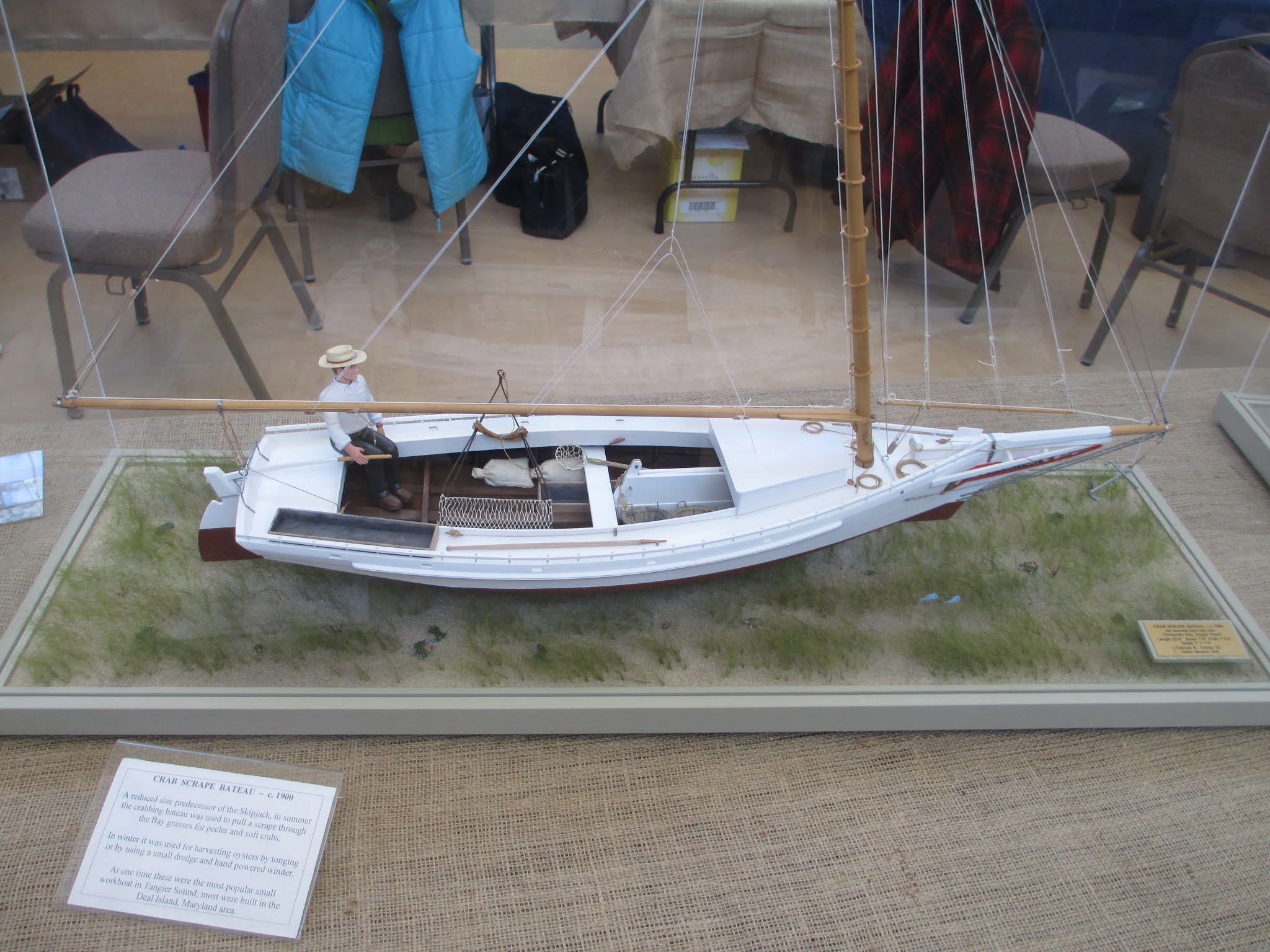
Chesapeake skiffs by Ed Thieler, Easton, Md...


Eddie Somers, Crisfield, MD...


Tuesday, December 15, 2020

What I miss...

 
Mid-Atlantic Small Craft Festival, St. Michaels, MD, October 2013


What's in Your Ditch Bag?

New Tech Bights article now out in issue No. 135 of Small Craft Advisor magazine .