Showing posts with label MacGregor. Show all posts

Tuesday, May 17, 2022

What's in Your Ditch Bag?

New Tech Bights article now out in issue No. 135 of Small Craft Advisor magazine.


Tuesday, December 22, 2020

More on Flotation, and Masts


In a previous article I mentioned a couple of options for replacing or adding flotation to your boat. I pointed out that dry bags and wakeboat ballast bags were more economical than purpose-built flotation bladders. But since small boat folk are usually pretty good DIYers, how about making your own bladders? If you're interested, here's a link to Mik Storer's article on making them, www.storerboatplans.com/boat/sailing-boat/cruising-dinghy/diy-pvc-buoyancy-bags-and-dry-bags-for-dinghies-and-canoes/ .

Materials that you need:
  • Bostik Unigrip 999 or 1669 adhesive
  • 18 oz Hypalon PVC fabric
  • Air valve

A good source for materials for making and repairing dry bags and bladders is NRS (www.nrs.com), a top dry bag and raft manufacturer, as well as supplier for river running gear. They sell fabric, adhesive, and valves. And they have a bunch of useful how-to pages...

Sailrite (www.sailrite.comis another good source of PVC-coated materials, typically used for biminis and tarps (lighter weight and considerably cheaper than NRS):
  • HH-66 adhesive
  • 18 oz Shelter-Rite fabric
  • 13 oz Weblon Regatta

Since I'm pointing to him, I should also mention that Mik Storer is probably best known for his iconic Goat Island Skiff design. And if you want to know anything about how to build and rig a lug sail, and get the most performance out of it, his website is where you should start. I noticed that he also has a couple of articles on windsurfer masts used for spars -- www.storerboatplans.com/plan/gis/windsurf-mast-lug-yard-goat-island-skiff/ . He's one very frugal sailor...

Friday, December 18, 2020

Small Boat Flotation and Howard Hughes' Flying Boat


Some boats, like Boston Whaler skiffs and MacGregor powersailers, are built with flotation foam between the inner and outer laminations. Roger MacGregor was quite willing to flood any of his boats just to prove that they would not sink and would keep you safe, even though they were water-ballasted. And if you check out his old sales videos on YouTube, he even did it a few times. 


When the boat is not built with integral flotation, you might have to really look for it. For example, the “built-in” flotation on a stock Potter 15 consists of three parts. The easiest-to-see, assuming it's still there, will be two large blocks of styrofoam, one located beneath each of the cockpit seats. They keep the aft end of the boat afloat in the event of cockpit and cabin flooding. Each block provides about 3 cubic feet (1 foot x 1 foot x 3 feet long) or 192 pounds (3 cu-ft x 64 pounds of seawater per cubic foot) of flotation. Since the empty weight of a Potter 15 is about 500 pounds, the foam blocks in the stern are not enough to keep the boat afloat if it floods. 

The rest of the flotation is much harder to find -- because it is underneath the cabin floor. On the forward end of the boat there is a bulkhead that crosses the hull under the mast support. If you open up the cabin floor panels and look forward, you will see it. Foam fills the space ahead of this bulkhead to support the cabin floor and to keep the forward end of the boat from sinking. Unfortunately, without removing the floor or cutting an inspection port, there is no easy way to inspect the forward flotation. Fortunately, Potter's builder did provide a way for any water that gets into the boat to drain back to the cabin, where you can get at it. I estimate the volume of under-floor foam is 6 to 8 cubic feet, or 300 to 400 pounds of flotation. 

Add the three parts together and you come up with 700 to 800 pounds of built-in foam flotation. This is enough to keep even a loaded Potter from sinking, and there are old sales photos showing a young woman standing in a scuttled Potter full of holes in the hull. If you find that photo, note that there are no waves, it is nice calm water. Sufficient flotation is necessary, but not sufficient to keep you safe. Placement of the flotation -- where it is located -- is the other aspect that needs to be addressed. How many runabouts have we seen where the occupants end up clinging to a capsized hull? Because most of the flotation is under the floor, a big enough wave could roll a flooded hull and it will "turtle" -- the flotation in the floor now up high. So, the best flotation is up high -- near the gunnels -- to reduce the tendency to roll over. Since much of the flotation of a Potter (and many other small sailboats) is also low in the hull, they have the same predilection to turtle when flooded, especially if the centerboard is not locked down or is lost, and the mast fills with water. Steve Potter described capsizing his Potter 15, and explains why it happened (“Capsize at Clipper Cove,” Small Craft Advisor, No. 56, March/April 2009, page 22). His experience is applicable to a lot of production and home-brew small craft.

If you find that the styrofoam blocks in your Potter (or other boat) are still under the cockpit seats, be aware that they can work themselves loose, which is not a good situation. And if they got loose before you bought the boat, they might even be gone. Some Potters have been "customized" with hatches cut into the seats, and the foam was removed to increase storage for anchors or fenders. Yikes! Hope the hatch covers stay secured. So it is important to make sure that enough flotation is still in the boat, and that it is secure and not rattling around. If the blocks are loose, then you can try to re-secure them using a good polyurethane construction adhesive such as PL Premium (test to make sure that it doesn't dissolve the foam). If necessary, fabricate a suitable “wedge” (using polystyrene foam sheet) to force the foam block up against the bottom of the cockpit seat. 

If the styrofoam blocks are saturated with water (it's an "open cell" foam) or if they are missing, you might want to replace them. Extruded polystyrene foam sheet, which is closed-cell and won't absorb water, is available up to 2 inches thick. The 2-foot wide sheets are especially useful and each piece, 2.8 cubic feet of foam, is good for about 170 pounds of buoyancy. Build up a “block” and secure it using PL Premium adhesive. It is also possible to add even more flotation by sticking polystyrene foam to the bottom of the underside deck surfaces. And if you are planning some cool weather sailing, more foam can be used to line the inside of the cabin walls. In the Potter, it is possible to insert additional sheet foam between the cockpit seat back and the hull -- the best place for more flotation.

An option to sheet foam is to add flotation or buoyancy bags, which have become common on small boats, kayaks, and canoes (e.g., www.nrs.com/category/3049/kayak-touring/float-bags). In addition to adding buoyancy, these devices also reduce the amount of water that might fill the cabin or compartment. Buoyancy bags are not cheap, and the selection seems fairly limited -- there's just not that much demand. In contrast, dry bags, used for rafting and camping, are readily available from many sources and come in volumes of up to around 90 liters (seatosummitusa.com/collections/outdoor-gear-dry-bags/products/ultra-sil-pack-liner). And the prices are very reasonable. To replace a Potter 15's styrofoam block (displacing 3 cubic feet) you would need a flotation bag with a volume of at least 85 liters (1 cubic foot is equal to 28.3 liters), and a quality dry bag would run about $50. You can fill them with inflated play balls or beach balls -- they are very cheap (find them on sale in the spring), tough, and can be inflated using any pump with a needle. If you are old enough to remember Howard Hughes, you might have heard of his gigantic flying boat, the "Spruce Goose," so called because it was built toward the end of WWII using laminated plywood -- steel and aluminum was in short supply due to the war effort. 


After it's single test flight in 1947 -- for about a mile at a maximum altitude that was under a 100 feet -- the plane was stored in an air-conditioned hangar Long Beach, CA until 1993. It's now at the Evergreen Museum (www.evergreenmuseum.org/the-spruce-goose)Hughes had already survived several airplane crashes during test flights of his planes. So he filled the plane's cargo compartments with beach balls secured with nets to provide removable positive flotation -- just in case.


Unlike the "Spruce Goose," the most effective position for these flotation bags in
 small boats is probably at the level where the flooded boat will settle, around the gunnels. And they should also be secured so that they'll stay put in a capsize (unlike in the above photo).

How about attaching flotation to the outer gunnels of a trailer-sailer, like on the hard-bottom RIBs? A string of fenders can add a lot of flotation, but they are expensive. A 22-inch fender gives about 1/2 cubic foot of buoyancy and costs around $30, although you can frequently find them on sale. And if you can figure out how to lash it to your gunnels, Duckworks sells a 9 x 60-inch beach roller ($70) that can double up by providing about 2 cubic-feet of additional flotation (duckworks.com/beach-rollers/). Wakeboats use "ballast bags" that are rated by pounds of water. A 375-pound bag has dimensions of 14 x 65 inches, or 6 cubic-feet, for $100 (www.evo.com/fat-sacks/straight-line-big-bag-375-ballast). That's a lot of flotation if it is pumped up with air instead of water. Two 350-pound ballast bags (5 cubic-feet per bag, $135, at www.wakemakers.com/launch-pad-350-twins.html) would make ideal replacements for the styrofoam blocks in the Potter's stern.

For lots of reasons it's important to load the boat so that the heaviest items, such as water bottles, anchors, and chain rodes, are secured as low as possible, ideally between the cabin floor and the hull bottom. In addition, it is useful to store lighter items, such as clothes and sleeping bags, in sealed “dry bags” that are secured as far forward and as close to the deck as possible. This puts flotation up high and, together with a couple of flotation bags up high under the cockpit seats, should help keep the boat from turtling if it is flooded. If heavy weather is expected, right-side-up buoyancy can be further enhanced by securing dock bumpers to the gunwales using the deck cleats and railings.

And it’s worth repeating the obvious: the Potter -- and any small cabin boat -- has it's maximum amount of flotation in its cabin. If the cabin hatch boards are in place and the sliding hatch is closed during a knockdown, much of the green water will be kept out of the cabin, the boat will stay afloat, and it cannot turtle. Water inside the cockpit should drain out (make sure the plug is out, or is easy to pull out). I sail my Potter with the hatch boards in but the sliding hatch open, for ventilation and so that I can get to stuff in the cabin, and the odds are still excellent that a knockdown will not cause cabin flooding. And w
henever the wind pipes up, the best insurance is to "batten down the hatches" and I close up the cabin.

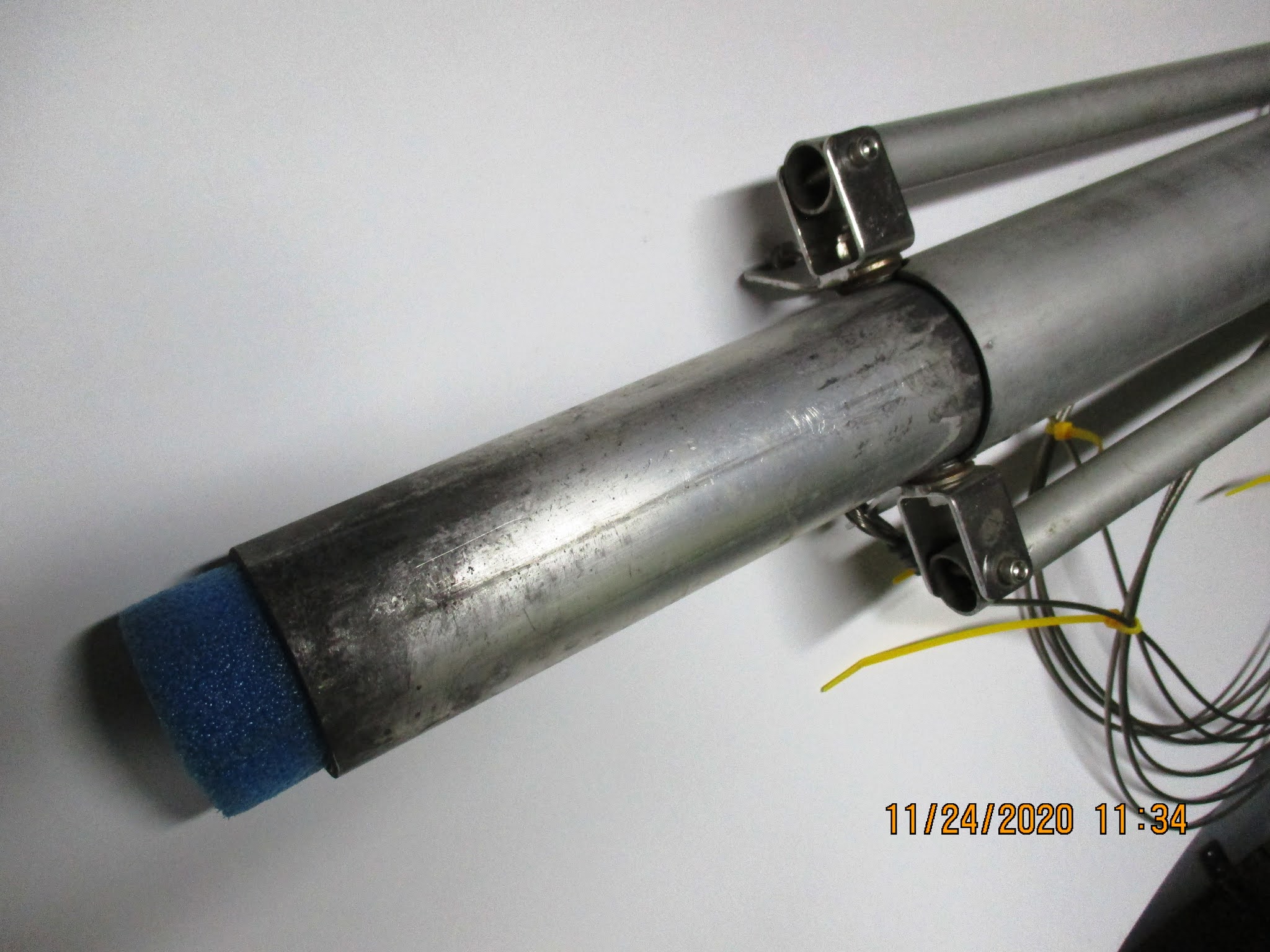
The Potter 15, like many small boats, has a hollow aluminum mast and boom, which can help resist the tendency of the boat to capsize if it fills with water if the ends of the mast (and boom) are plugged. The spars don’t have to be “watertight,” even a wad of soft foam is better than nothing. If the mast is plugged it may slowly fill with water from all the little holes at the fittings, but until it does you have about a half cubic foot of buoyancy (30 pounds, or more than an typical inshore life vest), which should help keep the mast up off the bottom. If you sail where “turtling” into mud is a distinct possibility, then adding a masthead float (a la Hobie cat) might actually be the best solution, at the cost of windage and weight at the top of the mast.

In Roger MacGregor's sales video for the powersailer, was the ballast tank flooded, or empty Answer: flooded.

Tuesday, December 1, 2020

MacGregor 19 Mast Stepping

The mast on my Potter 15 is 15-1/2 feet long and weighs about 10 pounds. Raising the mast is relatively easy as long as the shrouds don't snag. The mast for my M19 is nine feet longer and weighs more than 45 pounds. A mast-raising failure could be catastrophic, and I needed some method of assist to single-hand it. I had difficulty trying to figure out how mast-raising on an M19 was executed; the photos in the owner's manual did not jibe with my reality...

The MacGregor 19 was built with a pivoting mast step and has provisions for lateral baby-stays between the middle of the lower mast section to anchors that are outboard on the forward cabin top. It took some effort to find, but below is a photo of the set-up (today I cannot find the picture's source, but thank you for the clearest explanation of what's going on. And what a great-looking dodger -- something that I will return to). As you can see, the babystays are attached to cabin top using the flat deck eye straps that are just outside the bullet blocks, and they are co-linear with the pivoting axis of the mast, which is critical for stabilizing the mast until the shrouds can take over.


After more searching around the internet I found a photo of a cable with a fitting that would mate with the flat deck eye strap and presumably a mast with a keyhole slot. Lo and behold, Blue Water Yachts (www.bwyachts.com), the aftermarket parts supplier for MacGregor sailboats, still sells the mating clip (BWY #34201X0) and the flat straps (BWY #34211X0), although not the cable assembly.

I don't have slots in my M19 mast. Instead there are two holes that are 5’-7” above the foot of the mast. I used them to attach two mast tangs. The flat shackles on the cabin top are 24 inches from the centerline, and the babystay mast support angle is about 70 degrees. I believe this is very close to what is shown in the owner's manual, which shows a rope cleated to the mast. Instead of steel cables I used a couple of polypro cam straps threaded through the flat deck eye strap that ran up to the mast tang on each side.

Two mast crutches were supplied with my boat; they plug into a socket on the transom crossbar. A short, 6-inch crutch is used during transport, and a 2-foot long crutch is used to increase the mast lifting angle during raising and lowering.

There was no gin pole that was included with my boat. The short crutch could possibly be used as a gin pole, but it would need an extension tube to slip on the end. The tubing would need to be pretty small diameter to fit. For a DIY project, Blue Water Yachts sells arms that can bolt onto larger-diameter tubing (BWY #34231V0).

One version of the M19 mast raising process (described in the owner's manual) uses one of the winches. The gin pole is attached to the front of the mast step and the forestay is then attached to the end of the gin pole. A block is temporarily clipped somewhere near the bow, and a sheet is run through the block to the end of the forestay. With the gin pole perpendicular to the mast, a block-and-tackle (the mainsheet) is strung between the pole and the forestay anchor. Or one of the jib winches is used. Take the lazy end to the winch, give it a crank, and up she goes. Unfortunately, working in the cockpit is not the safest place since you will be standing right under the mast. And once you've got the mast up, the tricky part is extracting the forestay and locking it into the bow fitting. Thinking ahead, you can belay the mast upright if you shackled the jib halyard to the bow and cleated it off on the mast. What the manual doesn't mention is that this operation is best performed if there is at least one more person besides the person on the winch, a luxury that I don't have. I sail single-handed, and I don't want to depend on boat ramp "volunteers" for help.

Another mast raising system for the MacGregor powersailers incorporates a dedicated near-vertical strut that attaches to the mast step and has a small hand winch, similar to ones used on trailers, attached near the top end. Here is a good video of the home-brew rig in use, www.youtube.com/watch?v=NRaJxP50ZS8. Judy Blumhorst, the well-know West Wight Potter sailmaker, posted an great video with commentary of how she manages her Potter 19's mast, www.youtube.com/watch?v=aIXH9jos-cI. Finally, this video shows the details for the latest MacGregor 26M powersailer mast raising system, www.youtube.com/watch?v=z69AEM101x0. So I had lots of great examples to study.

I assembled my crane using some aluminum C-section and a trailer winch from my parts box. The bottom of the aluminum is bolted to the front of the mast step. The top end of the strut is fixed to the mooring cleat using a cable or a length of low-stretch line. Baby stays to anchor points on the chainplates fix the “mini-mast” strut. The winch cable is attached to the mast and is used to raise and lower it.


Note that I added an extra set of stays from the crane to the bullet blocks on the cabin top (the ones normally used as fairleads for the jib sheets). This keeps the crane rock steady throughout the mast raising process.

The advantage of this approach is that the operator has a stable winch position that is close to the mast, the forestay is loose (which will need to be released or attached to the bow fitting) and you are not underneath the mast at any point. In addition, being close to the mast allows the operator to stabilize the rig if something should need it (like a fouled shroud). And the winch lock gives positive control and can hold the mast at any elevation. And the smallest trailer winches, rated at 600 pounds, are more than strong enough to do the job. I've also found that I've got a good view of all the shrouds while I'm cranking, and I can stop at any point if I need to fuss with something. It's much better than working down in the cockpit.

This crane system is simple and safe, so it will stay in my M19 kit. I don't need any help to get the mast up and down with complete control. The only downside is that there's one more piece of gear that I need to carry. I haven't tried raising or lowering the mast while out on the water, but I think that this system would work infinitely safer and with more control than the method shown in the owner's manual if you are sailing short-handed.

Friday, November 27, 2020

MacGregor 19 Rudder Mod

All of the MacGregor powersailers have twin kick-up rudders that are used both for sailing and when the outboard is running, even at speed. On the M19, the motorwell is too narrow to allow the outboard to swing more than a few degrees. Unlike the later 26X and 26M models, the motor and the rudders are not connected together on the M19.

The kick-up rudder blades are hinged on custom stainless steel rudder posts. MacGregor used sacrificial plastic shear pins, nylon bolts, or wooden dowel pins to hold the hinged blades in the down position. The photo shows the rudder blade down, using the stainless steel "transport" pin (which I use to lock the blades up for trailering, not for sailing!).


Running aground breaks the plastic or wood pin and (hopefully) protects the steering mechanism and rudder blade from major damage. But with the blade up it's now nearly impossible to steer the boat, and the blade could even break if the boat is running at speed. In the worst case, the stress could rip out both the rudder and rudder post. Even though the original rudder blades are rather substantial construction, it looks like many M19 owners have replaced their rudder blades, for one reason or another. They are available from Blue Water Yachts (www.bwyachts.com), the aftermarket part supplier for MacGregor sailboats. Or from Ruddercraft (www.ruddercraft.com, only $559).

Why not just motorsail using the outboard to steer using it if the pins should shear? As mentioned above, on the M19 the 40-hp outboard can't swing more than a few degrees, and the motor is not connected to the tiller arm. Besides the issue with steering, how do you replace the pin when you're out on the water? And you don't have a boarding ladder? It would be prudent at this point to fire up the outboard, drop the sails, and motor back to a dock to effect the pin replacement.

The rudder shear pins have contradictory requirements: they must be strong enough to keep the rudders down while planing at full speed (according to the specs, up to 25 mph), but still able to shear through if you hit something solid. I did not expect the plastic pins that came with the boat to last very long on the Chesapeake Bay, particularly in the places where I gunkholed with my Potter 15. The spares included with the boat were clearly homemade home-brew replacements -- so it looked like I needed to devise an alternate approach. I definitely did not want to break a rudder blade, or a steering post ($185 for a replacement), or worse.

The original M19 rudder blades appear to be solid fiberglass and weigh about 14 pounds. Many of the more common 26-foot powersailers, and a few M19 owners, modified their blade systems and used multi-part uphaul and downhaul lines. However, this seemed much too complicated to me, and required a lot of parts and some machining. Instead, I borrowed a tried-and-true Potter mod -- the push-pull control rod -- which, according to Potter lore and typical of the breed, was originally conceived using a broken golf club handle (see, for example, Harry Gordon's or Wayne Pierce's “Rudder Blade Push-Pull Control Rod... " rudder modifications in the WW Potter Owners Association archive). My push-rod prototype was constructed using scrap wood and some scrap copper water tubing that was sitting in my shop. I attached a spare plastic bimini fitting to the top of each rudder blade, flattened the end of the copper tubing, and attached it to the fitting.


To top of the copper pipe is retained by a wood crosspiece, which has holes the the copper pipes that are drilled just slightly oversize, so there is some friction. It worked very well until I oiled the wood to protect it.


This modification is simple and cheap; but the rudders still would kick up when the boat was powered up and there was a lot of pressure on the blades. My contribution to the Potter mod is to rig the “golf clubs” with a thin line “stop” to hold the blades down. The lines are stretchy enough that if the rudder blades do connect with something, or if I drive the boat fast enough, they will lift a bit, but I will still have enough blade down to control the boat. Next I'm going to replace the wood crosspiece with some PVC lumber, and then I won't have to bother with varnishing or painting (the crosspiece above looks pretty ratty, after one season). I can think of many ways to control the friction between rods and the crosspiece, but all of them increase the parts count and complexity of the mod. So I will retain the line-cleat arrangement for now.

As I said earlier, during transport on the trailer I lock the rudder blades up using those stainless steel pins. The bottom of the rudder blades needed some touch up epoxy. Once the repairs cured, I buffed them up the lower part of the rudder blades with 50 grit sandpaper and spray painted them with "Kubota" orange spraypaint from my local hardware store.


Thursday, November 26, 2020

Going; going; gone. Well, almost...

No, I'm NOT talking about politics. As I'm doing research on the internet, more and more of my bookmarked links lead to "not there anymore" pages. This post is to help me remember that sometimes you can still find information if you look for it hard enough. 

International Marine, manufacturer of the West Wight Potter sailboats until it closed in 2015, provided a treasure trove of information gathered from Potter owners and ex-owners. If you were a new owner of an old Potter, this website was invaluable (thank you, Ken Lange). When the company closed, the Potter lore appeared to be lost. Fortunately, most of the information on the old website still exists (for now at least...) using the Wayback Machine,

https://web.archive.org/web/20160401020516/http://wwpotterowners.com/

As a new owner of a 25 year old MacGregor 19 Powersailer, I found the "dougpile.com" website to be a great starting point for info and mods, including a copy of the M19 Owners Manual. The original website is gone, but most of that content is still at

http://web.archive.org/web/20161014125752/http://www.dougpile.com/mac19/

A couple of years ago, I found another great MacGregor sailboat resource. I spent time perusing the forums, especially the section of "mods," then dreamed of the mods that I would undertake on my new-to-me M19. After a few months, the website disappeared. The boat has been parked and the projects have been halted for a couple of seasons. 

Recently I went looking for a nugget of information related to outboards and prop selection using the usual Google search. Lo and behold, I found that the old Mac website has reappeared, with a new and sleeker front page, a lot of recent posts on the forums, and more mods. More fun this winter; and dreams of new Mac19 projects! Here's the link,

www.macgregorsailors.com

To give equal time to the Potter owners (or potential owners), the best forum that I've found is at at the Trailor Sailor website. Here's the link to the Potters (there are also forums for other brands like Nimble, Com-Pac, Montgomery, and Precision), 

https://forum.trailersailor.com//forum.php?id=2


Happy Thanksgiving.


Wednesday, November 25, 2020

OMOB (One More Old Boat) MacGregor 19 Powersailer -- Part 2

You can’t get a really good look at a used boat or car until you are alone with it. Since I bought the boat in November, I used the off-season winter months for research; I started this article to document what I found...Today, as the boat and information both increase in age, I'm finding that lots of M19 knowledge and lore is slowly disappearing, year by year...


The original owner of my M19 powersailer bought the boat in 1993 in Ohio and sailed her on the upper Chesapeake Bay. It looked like he set it up for for single- or short-handed sailing. He used the boat for over 20 years, then donated it to a maritime museum. I bought the boat in the fall of 2017, and no one knew much more about him or about the boat than that. The best place to find current information on MacGregor powersailers is at the MacGregorSailors.com forum, https://macgregorsailors.com/forum/. There are plenty of comments from 26X and 26M owners, but very little about the M19.

Mast and Standing Rigging


The 23’-8” mast on the M19 is a “two-part” masthead rig and can (theoretically, at least) be stored inside the boat. That is what is shown in the original advertisement and sales brochures and videos of the MacGregor powersailers. What I quickly learned is that "storage" in this case means “end of season” -- or longer-term --storage. It does not mean that the mast is easily dismantled for trailering from point A to point B, or while on the water. A heavy coupling that slides into the mast ends also supports the tubular spreaders and joins the two mast sections. Getting them apart, and back together, is a task that I’m not going to repeat very often (if ever).


The mast cross-section is robust for a 19-foot boat: 4” x 3” (similar to Dwyer DM-6). The stainless steel mast step is hinged. A 3/8-inch bolt is the pivot pin. The step has a second set of holes on the bow end. Presumably these are for the mast-raising gin pole. It does not look like the boom is configured to serve as that element. The lower mast has two cleats for the halyards, but my boat has extra hardware, turning blocks and organizers. They are not original and were added for bringing the halyards back to the cockpit.


There are two flat straps bolted to the forward cabin top corners (below the deck organizer in the photo above). They are original, not added, and are in-line with the mast step. I assume they are the attachment points for the two baby stays that stabilize the mast while it is being raised or lowered. Presumably the ends of the baby stays have special clips that toggle into the straps. There are also two bullet blocks that are toward the forward edge of the cabin top, about 18 inches away from the mast. They are also are original, not added later. Are they fairleads for the jib sheets? Maybe, the owner's manual does not tell. But the manual does show them being used as lashing points for "optional" mast-stabilizing baby stays, which were attached to a set of cleats on the mast that are about five feet up from the step. On my M19 the cleats are only 40 inches up the mast. That's not much stabilizing for a heavy mast that's almost 24 feet long...just sayin'. The mast on my M19 does have two holes, one on each side, further up the mast, about where the alleged cleats would be located. Perhaps a set tangs for connection to the babystays could be attached there, in lieu of another set of cleats.

The mast has upper and lower shrouds that terminate at chain plates bolted to the hull. The chain plates are strong enough to support the boat and were used during assembly in the factory to lift and move the boat around. The shrouds and stays are 1/8-inch 1x19 stainless steel cable with swaged eyes. The lower ends terminate with stainless steel "tang" adjusters, not turnbuckles. Not only are these cheaper devices, but they are, in my opinion, stronger and more reliable on a small boat where the mast is being raised and lowered frequently -- as long as the ring-dings are taped. The forestay carries either the hanked-on a working (100%) or a genoa jib. The M19 has a fixed backstay that is anchored to the aft stainless steel rail above the transom. The mainsheet and the steering is also anchored to this rail, so it’s a pretty substantial structure.

The boom is 8’-6” in length and its cross-section is 3” x 2-⅜” (Dwyer DM-4 is a close match). The gooseneck is 2’-3” above the foot of the mast and the cabin top. When the hatch is open you can stand up in the cabin without hitting your head on the boom. But the clear height in the cockpit is only about five feet. As a result, some M19s have extended masts and raised booms to increase the cockpit clearance.

The M19 owner’s manual specifies that the mast should rake 4 degrees aft. Blue Water Yachts (who provides MacGregor aftermarket parts and support) suggests that the mast rake should be 6-8 degrees (“more than most trailerables”). Raking a mast further aft tends to reduce excess lee helm and improve upwind pointing. The MacGregor manual indicates that the mast rake is correct when a small weight attached to the mainsail halyard should touches the cabin top about 20 inches behind the mast (24 inches equals 5 degrees of rake; 30 inches, 6 degrees; and 40 inches, 8 degrees). The rake is measured with “the boat in the water, the water ballast tank empty, no one aboard, and the weight of a 40-hp outboard on the transom.” I guess you need to be standing at a dock to figure this out.

The forestay and upper shrouds should end up being snug once the rake is set. The backstay is then set tight. The lower shrouds are adjusted to take out any mast curve. The weak point on this rig, according to the owner comments, is are the hinged, tubular aluminum spreaders, which might collapse under load. And many owners upgraded to fixed spreaders with heavier tubing. The bracket for the upgrade, as well as replacement shrouds and stays, appears to be still available from Blue Water Yachts

Sails


Blue Water Yachts (http://www.bwyachts.com/), an aftermarket part supplier for MacGregor sailboats, provides an interesting commentary on the M19 sailplan...

The 19 is a stiff, stable boat with a fair amount of hull drag and smallish rudders, it wants all the sail power you can put on it. Unless you sail in a very high wind area, almost everyone prefers the balance and performance of the boat with the 150% Genoa. Some very early 1992 models had a simple 3 wire rig with no spreaders and the headstay only about 3/4 of the way up to the masthead. Few of these boats were rigged to run a 150% Genoa, just a tiny 100% Jib. Many of these boats have been re-rigged to the newer masthead rig with spreaders. Sheet winches were an option on the 19, if your boat doesn't have winches on the cabin top, you will need to add them to use a 150% Genoa." (https://shop.bwyachts.com/articles.asp?id=257

My M19, built in 1993, has double shrouds and is the masthead rig. I'm sure I've got the original Doyle main sail that came with the boat. The loose-footed mainsail is spec’d at 91 sq-ft and has one reef that is 5-½ feet above the foot, bringing the area down to around 50 sq-ft. On many other boats this reduction in area would be the “second reef” (the first reef being about 12% of the luff length, or 30 inches for this sail). I suspect this was done just to save money at the sailmaker, and because M19 powersailer sailors don't reef. They just fire up the 40-hp outboard and go waterskiing.


The hanked-on working jib, also from Doyle, is specified at 76 sq-ft and is cut with a very high clew to make tacking easier. The sheets are led inside the shrouds through fairleads on the cabin top, then to two single-speed Lewmar 6 winches, and followed by cam-cleats on the cabin-top. The jib does not use turning blocks, and the fixed fairleads are 94 inches aft of the tack on the front of the cabin top, 19 inches off center, giving a theoretical sheeting angle of about 11 degrees. The info provided by Blue Water Yachts suggests that the relatively small jib does not need winches for trimming, and I confirmed that once I had the boat out on the water, but they are nice to have.


The genoa is 152 sq-ft in area, and the sheets are run outside the shrouds to turning blocks located at the front of the cockpit, then forward to the winches. If there is a cruising spinnaker (which I don't have), the turning blocks are relocated to the rear of the cockpit, temporarily strapped to the aft mooring cleats. A lot of owners added a track on the cockpit rail to accommodate an adjustable block. I can’t see that ever happening on my M19 unless I decide to play with a light-air screecher some day in the future.


Replacement sails, as well as other parts for the M19, appear to be still available from Blue Water Yachts. When I bought the boat you could also get new sails from Hyde Sails (who also supplied sails for the Potter sailboats). They showed a 97 sq-ft mainsail, a 105 sq-ft No. 3 jib, a 123 sq-ft No. 2 genoa, and a 137 sq-ft No. 3 genoa. Unfortunately, Hyde is not longer building sails for MacGregors, or for Potter boats...To borrow a phrase from Kurt Vonnegut's "Slaughterhouse Five," so it goes. You can still buy a sail kit from Sailrite and then build it yourself.


Running Rigging


The halyards were led through turning blocks at the base of the mast, through a couple of deck organizers on the cabin top corners, then aft to Spinlock cam-cleats. In addition to the stock cam-cleats that followed the jib winches, there was an extra set of cam-cleats.


And the centerboard was rigged to operate from the cockpit with a third Spinlock cam-cleat. The mainsail has luff slides to make it easy to get tie sail up and down the mast track. The hanked-on non-furling jib had been set up with a positive “downhaul” line, as evidenced by the guide attached to the bow pulpit and to the forward cabin top. And there was a “tiller tamer” at the helm. These are many of the same changes that I made on my Potter to make it easier to sail single-handed. And buying the M19 already set up for single-handed operation saved a lot of effort and money. I still have not figured out why there is an extra set of cam-cleats around the winches, and these will be removed.

In any event, I could not detect that any kind of quickie reefing was set up, although the boom has a hook at the tack, and the outhaul could be reset through the reef cringle on the leech (if you have the time and crew to do it, and the conditions are not too wild). You could probably set up a reef on the dock, and then shake it out, but it would be a pain to put the reef in if there was any serious breeze. The boat does have the optional vang to control sail twist, but only a rudimentary outhaul to adjust the sail flatness. In typical frugal MacGregor fashion, the outhaul consists of a cleat on the end of the boom. The original owner had added a Harken lazy-jack system (a plus!), which is consistent with the single-handed set-up for the halyards, the jib downhaul, and the centerboard. 

Centerboard and Rudder


As mentioned Part 1, a weak point on the M19 and 26X powersailors, which have centerboards, is their centerboard pendant and pulley -- something I neglected to check during my initial inspection. The board raising system consists of a multipart pulley system on the cabin floor that is connected to a stainless cable pendant. Notice, in the photo below, that the centerboard control line runs up the mast. There is another turning bullet block near the cabin top, and then the line heads aft, above the door to the "head", to a Spinlock cleat just inside the hatch opening. Theoretically it is possible to set the centerboard from the cockpit. Turns out there is a lot of resistance in a couple of 90-degree changes using regular braid rope, and this mod needs some work.


Before I settled the purchase I did climb under the boat to inspect and verify that the pennant and lower pulley were in good shape. The centerboard is hollow and has fill holes so that the centerboard does not float. Once the boat is out of the water with the centerboard up, the water inside drains right out. There are warnings in the owner's manual and prominently posted on the boat that the centerboard must be raised if motoring more than 5 mph.

On the cabin floor there are two round ports that provide access into the ballast tanks. You can see one of them in the photo above. They also provide access to the centerboard pivot bolt and the pennant pulley attachment. Here's a drawing from the owner's manual showing what's down there.


The M19 has a very narrow motorwell, and the outboard can be turned only a few degrees off center, so the rudders do most of the steering under both sail and under power. The M19 is unique because the rudders are short and fairly thick and it is steered from a traditional tiller, not a wheel like the 26X and 26M powersailers. The tiller-to-rudder articulation is located well above the transom top, and a common complaint is “sloppy steering.”


As I inspected my boat, I found that rudder tiller arm brackets did not fit the rudder posts. A 1/4-20 bolt was used for attachment, but the brackets rocked on the rudder post, and they needed to be shimmed.

All of the MacGregor powersailers have twin kick-up rudders. The kick-up rudder blades are hinged on custom stainless steel rudder posts, shown in the photo below.


The kick-up mechanism used on the M19 is probably one reason why MacGregor sailboats are frequently characterized as "cheaply built." MacGregor incorporated sacrificial plastic shear pins, or nylon bolts, to hold the hinged blades in the down position. The photo below shows the rudder blade down, with the stainless steel "transport" pin (normally used to lock the blades up for trailering).
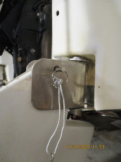

Running aground breaks the pin, like a fuse in an electrical system, and hopefully protects the steering mechanism and rudder blade. But it's now impossible to steer the boat. And how do you replace it when you're out on the water? And furthermore, the shear pins must be strong enough to keep the rudders down while planing at full speed (according to the specs, up to 25 mph), but still able to shear through if you hit something solid. On the shallow Chesapeake Bay, I did not expect the pins to last very long; and several spares -- clearly homemade replacements -- were included with the boat. Re-designing the kick-up rudders would be on the top of the list.

Outboard and Prop

The M19 is specified for outboards up to 40 hp, and my boat had a 1995 Mercury with electric start, electric lift and an alternator. This outboard is a two-cycle engine with oil injection. The water pump impeller and oil pump impeller were both replaced during the summer, just before I bought the boat.

The outboard came with a 10-1/4x14 prop. The shop that serviced the outboard said that prop was very likely the stock prop that came with the outboard back in 1995. There's a lot of discussion on the forums (a good one to look through is on MacGregorSailors.com, https://macgregorsailors.com/forum/viewforum.php?f=7) on the best replacement outboards for the MacGregor 26 powersailers, and the "correct" prop seems to be endlessly debated. What is clear, however, is that all of MacGregor powersailors require lower pitch props. Owners indicate that their boats wind up being propped like a big pontoon boat with lots of drag. If the pitch is too high, the engine will never run efficiently (or hit it's rated "WOT" -- wide open throttle rpm spec), it will run slow (due to excess slippage), have poorer gas mileage (for the same reason), and will "speed" at low rpms -- just when you want to crawl into a slip -- with the extra bite. One of the first changes I made was replacing the 14-inch pitch with a 12-inch pitch prop. And that is probably still too high, based on subsequent comments from the motor tech. And I will need to add a tachometer to figure this out.

Accouterments


The cabin hatch cover is hinged, not a slider. Pull the hinge pins and it is removable. On a mooring, that would be a nice feature. Be forewarned -- the cover weighs about 25 pounds and it will probably sink to the bottom if it gets away. Some M19 owners modified their hatch covers to act like the "pop tops" that were fairly common on many of the smaller O'Days and Catalinas, and even some Hunters, with cabins.

The original wiring for the cabin and navigation lights is a well-known weak point for MacGregors -- and for many other boats built more than 20 years ago. It looked like lamp cord, and nothing was fused. The previous owner re-located the battery from a compartment amidship to a shelf in the "head" and added a bilge pump in one of the aft storage compartments, just ahead of the transom. M19’s were not shipped with bilge pumps -- the bilge is occupied with the water ballast tank, and the fill channel runs down the middle to a gate valve on the transom. It's not clear what the pump was doing, but water had gotten back there at some point.

The motor well drains to a thru-hull fitting on the starboard side above the waterline. The hose connecting the motor well drain and the outlet had a tee for the output of the bilge pump. There was no gate valve on outlet, and the hoses had single hose clamps.

The boat came with a single 8-pound Danforth anchor with 10 feet of ⅜-inch chain, and 70 feet of ½-inch nylon rode. The rest of mooring setup was stock: one mooring cleat on the foredeck and one on each side of the stern. The Mac powersailers did not come with anchor line chocks up forward, and many owners added them. The previous owners installed a nice bimini the covered the cockpit, but it was too big to work with the sail rig and was removed. Adding usable shade is near the top of the list.

My M19 doesn't have and apparently never had a boarding ladder. If I ended up overboard, I would have to try to climb back up on the rudders or the outboard. I feel that this potential hazard needs to be addressed without too much delay. The factory ladder was a custom design, but still looks like Blue Water Yachts can provide one for about $300. The boat did come with a vintage porta-potti. I don't think it had ever been used (the "head" is not very big); I immediately removed it from the boat and stuck it in a corner of my shop. Let me know if you need one to complete your MacGregor restoration project and need OEM parts.

The boat came with the original trailer, also built by MacGregor. For a 20-year old steel trailer, it was in pretty good shape. I suspect that it was stored indoors when it wasn't being used. Maybe it hadn't been used much if the owner kept the boat in a slip during the sailing season. The lights had been replaced with LED tail lights. As I mentioned in Part 1, I replaced the tires and wheels as a matter of routine if they are more than five years old.

Sailing 


Searching the internet, I found useful information what to expect once I got the boat out on the water (see, https://macgregor.sailboatowners.com/reviews.php?mid=158 ). The experience of M19 owners indicated that the boat sails very poorly under main alone, and is difficult to sail upwind even in good winds (not too surprising considering that motorsailing upwind is where the outboard becomes very useful). Because the high cabin top results in significant windage, this boat struggles to sail through the wind unless care it taken to time the tack through the waves. Like a catamaran, the jib can be backwinded to force the bow over. By the same analysis, reefing the mainsail will reduce heel but will make tacking even more difficult if there is no headsail. So a storm jib might be a valuable addition if reefing is anticipated. The boat will perform much better if it is not sailed close to the wind, and unless the water is flat, one should probably bear off just prior to a tack to get enough power to make it through the wind. Unless the route is primarily a reach or run, the best hanked-on headsail will be a small jib that can easily tack inside the forestay triangle. Any larger headsail will require help to get across. A roller-furler and headsail designed for adjustable area is a high-priced alternative (similar to a screecher that you roll in the sail each time you tack).

What's in Your Ditch Bag?

New Tech Bights article now out in issue No. 135 of Small Craft Advisor magazine .